Model 6040, 16-Bit Digital Input/Output Module

FEATURES

  • 16 Digital inputs and outputs
  • Compatible with TTL and CMOS (6040-1)
  • Optic isolated inputs (6040-2)
  • Form C relay outputs (6040-2)
  • Automatic alarm responses
  • Programmable glitch capture
  • Input/Output status display


DESCRIPTION

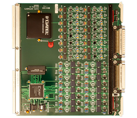
The 6040 digital I/O module provides 16 digital inputs for event recording and 16 digital outputs for control. The 6040-1 version has TTL and CMOS logic levels while the 6040-2 version has optic isolated inputs and isolated relay outputs. The 6040 may be programmed to automatically respond to the alarms generated by system input modules with preprogrammed digital outputs for the control of external equipment.


The 6040 is used to monitor critical events that are recorded with other data, and initiate programmed actions like start recording or emergency stop. The 6040-1 has non-isolated, TTL/CMOS compatible input and output levels. The 6040-2 has optic isolation, which assures that the DAS is isolated from large common mode voltages, ground loops, and transients that frequently occur in test installations. The output relays on the 6040-2 are single form C.


In normal operation, the digital inputs are captured coincident with the sampling of other DAS inputs. A "glitch capture" mode may be used to catch brief events, 100 nanoseconds or longer, that occur between sample periods. PI660 software includes screens for setting and reading digital I/O, monitoring of digital inputs for specific events, and programming digital output vectors in response to an alarm or input event. LEDs show the current status of inputs or outputs.


 

OVERVIEW


Measurement Type

Digital In
Digital Out

Input


Number (Input)

16 inputs, organized as one 16-bit data word.

Synchronization

Inputs are captured coincident within 50 nS of the sampling of analog signals in other Series 6000 input modules.

Glitch Capture

Enabled by software to detect and record events of 100 nS or longer duration that occur between sample periods. Reset on reading.

Input Logic Levels


Input Logic Levels

6040-1 - TTL/CMOS. Off is less than +0.8 Volts; on is greater than +2.0 Volts. Inputs protected to ±50 Volts.
6040-2 - Optic isolated. Off is less than 1.5 Volts; on is greater than 4.8 Volts. Input impedance is 500 Ohms. Inputs protected to ±50 Volts.

Input Isolation


Input Isolation

6040-2 - 450 Volts RMS between inputs and input to common.

Outputs


Number (Outputs)

16 outputs, programmed as one 16-bit word.

Programming

Output data word is loaded by program instruction during time when measurement data is not being sent to the computer. Latency will depend on system throughput rate and scan table programming.

Alarm Outputs

Pre-programmed output vector automatically set in response to alarm violation. Latency is less than 1mS from the digitizing of signal causing alarm.

Output Logic Levels


Output Logic Levels

6040-1 - CMOS. On is +4.8 Volts minimum; off is +0.15 Volts maximum from 1K Ohm source impedance.
6040-2 - One form C contact rated for 1 A at 30 VDC. Maximum voltage 220 VDC.

General


Mounting

Occupies one slot in Series 6000 enclosures.

Connectors

50-pin type D connector for inputs and 50-socket type D connector for outputs. Connectors are on the front and mates are supplied.

Temperature

0 to +50 ºC

Humidity

Up to 95% without condensation.

Ordering Information 


Ordering Information

6040-1 - Digital I/O Module, TTL/CMOS inputs, CMOS outputs.
6040-2 - Digital I/O Module, optic isolated inputs, form C relay outputs.