TEST TITLE BAR GRAPHIC

H! Very Important Here

test imageascuhvnbg isgha reigh SFOir gaprpg oszg awg hsubhp9

 

H2 Test Text for 403 Forbidden Error IP Whitelisting Check

zrgiuhig agseoghohzr gperhj og hae9 g ascuhvnbg isgha reigh SFOir gaprpg oszg awg hsubhp9 zrgiuhig agseoghohzr gperhj og hae9 gacuhvnbg isgha reigh SFOir gaprpg oszg awg hsubhp9 zrgiuhig agseoghohzr gperhj og hae9 gacuhvnbg isgha reigh SFOir gaprpg oszg awg hsubhp9 zrgiuhig agseoghohzr gperhj og hae9
gascuhvnbg isgha reigh SFOir gaprpg oszg awg hsubhp9 zrgiuhig agseoghohzr gperhj og hae9 g


test image


hEADLINE FIELD

hEADLINE IN EDITOR

acdh vyUfxbh d gzdjgoirdz[ofixb goiersjdgodbj gstdsjgoesirdj g

test image

BUY OUR STUFF 

  • EUF VH Gds
  •  grg zd
  • ea gshsdtx
  •  e5ags
  • d
  • e h
  • stt
  •  htrs
  • strh n
test

What is Lorem Ipsum?

Lorem Ipsum is simply dummy text of the printing and typesetting industry. Lorem Ipsum has been the industry's standard dummy text ever since the 1500s, when an unknown printer took a galley of type and scrambled it to make a type specimen book. It has survived not only five centuries, but also the leap into electronic typesetting, remaining essentially unchanged. It was popularised in the 1960s with the release of Letraset sheets containing Lorem Ipsum passages, and more recently with desktop publishing software like Aldus PageMaker including versions of Lorem Ipsum.

Modules

Here is some text. Text text text text.

Overview  

Enclosure Specifications

Series 6000 and 6100 Enclosures are common between the two product lines. Integrated A/D, data and sample rates noted in enclosure specifications apply only to the Series 6000 systems.
 
Data Format  

Data Word

16 or 32-bits, 2's complement binary.

Scan Table

Maximum format length is 65,536 samples.

Sample Rates

Multiple sample rates consisting of the highest sample rate divided by binary numbers. Highest sample rate is programmable with 1 uS resolution.
 
Data Interface  

Output Rate

Processor dependent, typically over 5 million 16-bit samples/second.

Latency

Processor and scan table dependent, typically less than 5 milliseconds.

Clock Stability

100 ppm over temperature range.
 
Operation  

Protocol

Control and data interface is USB 2.0.

Software

Windows 10 64-bit driver provides a high-level operating command set. Fully compatible with all implementations of PI660 operating software.

Control Inputs

TTL inputs for Start, Stop and Trigger assert flags in the header of output data that initiate software control operations.

Alarms

Warning and alarm buses may be independent or shared between enclosures and may initiate an output from a digital I/O type module.
 
Connections  

Calibration

15-Pin Type D mounted on rear panel. Mating connector supplied.

Control

9-Pin Type D mounted on rear panel. Mating connector supplied.

Synchronization

Category 5, enclosure to enclosure. 2-meter cable supplied.

USB

2-meter cable supplied.
 
Mechanical  

Power (Mechanical)

115 or 230 VAC, 110%, 47 to 63 Hz, 400 Watts.

Operating Temperature (Mechanical)

0 to +50 ºC

Humidity

95% without condensation.

Shock/Vibration

Normal shipping and handling of laboratory instruments.

Width

 View
19 in

Height

 View
5 in

Depth

 View
18 in

Weight

Approximately 25 pounds with all channel modules.
 
Control & Data Processor (CDP) and Operators Workstation (PCCOWU) (Optional)  

Input

USB 2.0 ports for up to eight 6000U enclosures. Additional 6000U enclosures accommodated by adding USB expansion cards.
 
Ordering Information   

Ordering Information

6010U - Enclosure, 4-slot, USB Interface
6095 - Redundant Hard Drive
CDP-1A - Control & Data Processor
CDP-1-DHD - Control and Data Processor, Dual Hard Drives
PCCOWU-DHD - Operators Workstation, Dual Hard Drive
Overview  

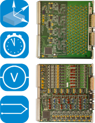
Measurement Type

4-20mA
Position
Thermocouple
Voltage

Analog Bandwidth

1 kHz

Excitation/Transducer Power

±12V
±15V
24V

Filter

4-Pole

Sample Rate (Digitizer)

Up to 10 kS/s

Analog Output

Monitor Output
 
Input  

Configuration (Input)

8 channels, differential, 2 wire with shield.

Range

±2 mV to ±10 Volts (±200 mV to ±100 V with optional attenuator).

Attenuator

100:1, ±0.2% (6013-HV).

Impedance

50 Megohms, shunted by 1,000 pF (1 Megohm with attenuator)

Protection

±50 Volts differential, ±30 Volts common mode. ±250 Volts differential with attenuator.

Type (Thermocouple Inputs)

B, C, E, J, K, N, R, S, and T.

Configuration (Thermocouple Inputs)

Differential, 2 wire with shield.

Type (Current Inputs)

4-20 mA input.

Configuration (Current Inputs)

Differential, 2 wire with shield.

Termination (Current Inputs)

200 Ohms
 
Excitation/Transducer Power  

Voltage

Regulated ±12 or ±15 Volts jumper selectable per channel (6013). 28 Volts (6013-24V).

Current

50 mA per channel, limited to 200 mA maximum per 8-channel module.
 
Amplifier  

Gain

Programmable 1-5000, in 1, 2, 3, 5 steps, with ±0.05% accuracy.

Gain Stability

±0.01%, ±0.005%/ºC.

Bandwidth

1 kHz
-3 dB

Linearity (Amplifier)

±0.01% for gains 0.1 to 1,000, ±0.02% for gains above 1,000.

Common Mode

60 dB plus gain in dB to 110 dB, DC to 60 Hz.

CM Voltage

±10 V

Zero (Amplifier)

Automatic to ±1 µV RTI, ±0.5 mV RTO.

Zero Stability

±5 µV RTI, ±1 mV RTO. ±1 µV/ºC RTI,
±0.2 mV/ºC RTO. Short term: ±2 µV RTI,
±0.4 mV RTO for 8 hours.

Source Current

±10 nA, ±1 nA/ºC.

Noise (10 Hz)

0.1 µV rms, RTI, 0.5 mV rms, RTO

Noise (1 kHz)

1.0 µV rms, RTI, 0.5 mV rms, RTO

Recovery

800 µS to ±0.1% for 10X overload to ±10 V.

Monitor Output

±3.0 Volts full scale, unfiltered.
 
Filter  

Type (Filter)

Four-pole, low-pass Butterworth.

Frequency

Plug-in, 4 Hz to 1 kHz, 10 Hz supplied. Alternate fiter characteristics and frequencies are available.

Other

Other filter characteristics and cut offs are available.
 
Digitizer  

Sample

Simultaneous sample and hold with ±50 nS channel-to-channel. Droop is less than ±0.005%.

Resolution

16-bits, two's complement output.

Sample Rate

Up to 10 kS/s per channel
10 kS/s

Digitizer Linearity

±2 LSB (±0.006%)

Continuity

Monotonic to 15 bits.

Alarms

Two alarms each with upper and lower limits that are programmable from negative to positive full scale. Limits checked on each ADC sample.

 
Calibration  

Voltage Substitution

Alternate input for external voltage standard. Programmable attenuation steps of 1, 0.1, and 0.01 with ±0.02% accuracy. Output of the attenuator is provided on a rear panel connector for calibration.

Zero Calibration

Amplifier input disconnected and shorted.
 
Mechanical  

Mounting

Occupies one slot in Series 6000 enclosures.

Connectors

Input connector is 50-pin Type D. Connectors are mounted on the front and mates are supplied.

Operating Temperature

0 to +50 ºC
 
Ordering Information   

Ordering Information

6013 - 8-Channel Voltage/Thermocouple, ±12V or ±15V Power.


6013-24V - 8-Channel Voltage/Thermocouple 28V Power.


6013-HV - 8-Channel Voltage, 100:1 Attenuator.


6013-I - 8-Channel Current Loop. 28 Volts, 0 to 20mA.


6081 - Screw Terminal Adapter.


6084 - 8-Channel Thermocouple Reference Junction.